FTelettronica
Transformer Matrix Ring Modulator
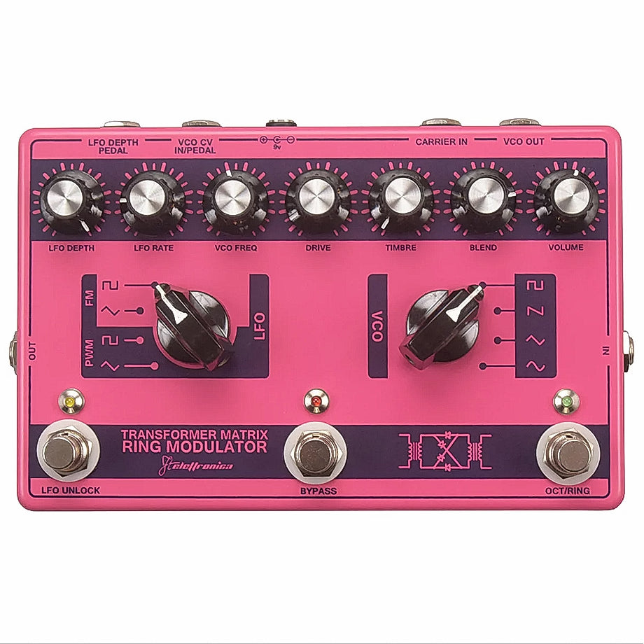
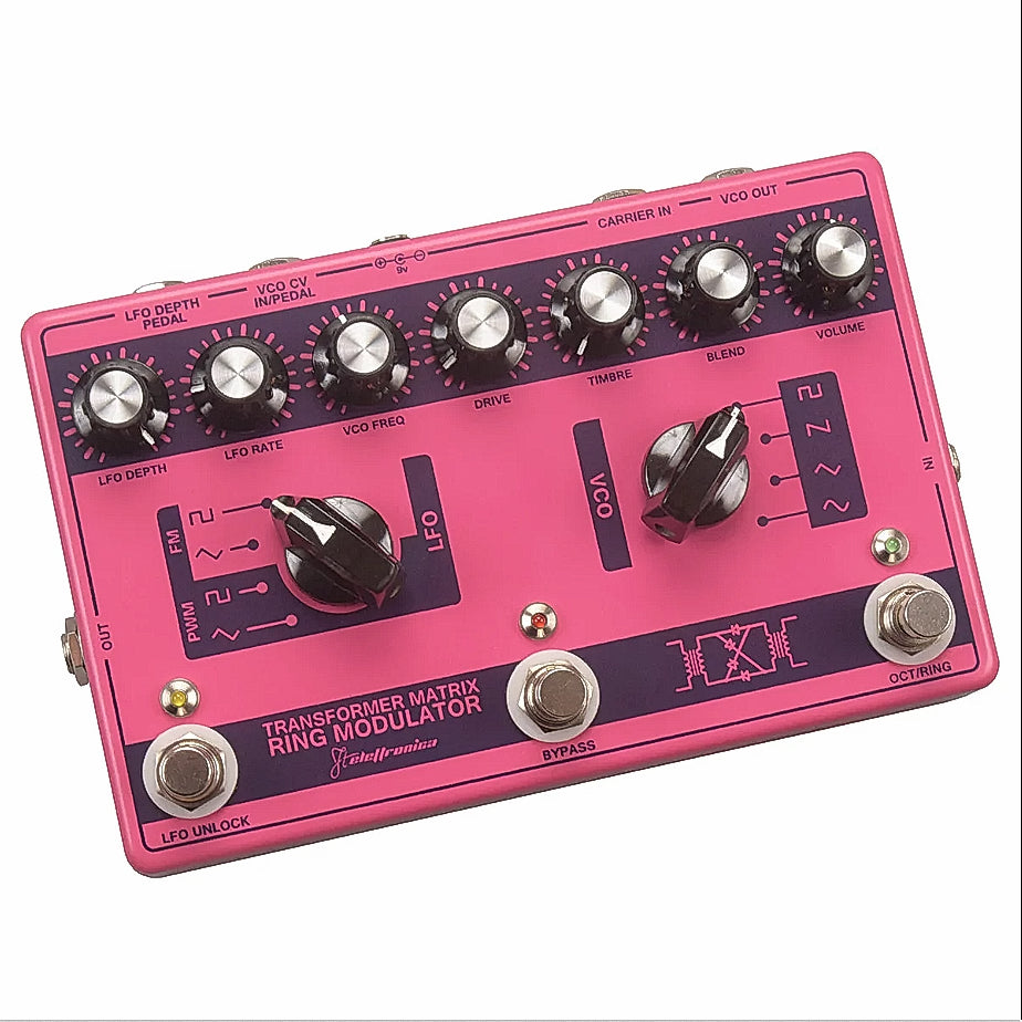
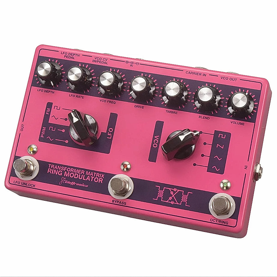
Transformer Matrix Ring Modulator
FREE 2Day Shipping
FREE 2Day Shipping
USA Free 2 Day Shipping
(Next Day in New England)
Canada NOW FREE!
Worldwide 30USD Flat Rate*(Wherever you are)
Flat Rate means no additional charge for more than one pedal.
No Hassle Returns
No Hassle Returns
Dimensions
Dimensions
Length 200mm
Width128mm
Height 65mm
Specifications
Specifications
9V DC Center Negative
30 mA
Couldn't load pickup availability
Input: You can connect a mic, instrument, mixer send or the output of another effect. Please note that the input level has a marked effect on the sound (see Drive). To attain a sufficient level a mic should be 200-600 ohm and connected via a suitable impedance matching transformer for high impedance 50kohm output (the inexpensive in-line balanced XLR to 1/4” jack type is ideal). The Ring Stinger is optimized for instrument level (-20dBm to -15dBm), which gives the best Drive range and Blend balance. Higher levels can he used but may require adjustment of control settings.
DC 9 volt Power jack. You can use a regulated and smoothed 9 volt D.C. power supply which must be stabilized mains and which has a standard 2.1 mm, negative – center. IMPORTANT: The purity of the VCO waveform depends on the supply voltage. (An impure VCO waveform, especially if modulated with a complex input signal, will drastically increase the harmonics flying around at the output. This will not generally give the most musical results, but can of course be used if desired. ) The Ring Stinger is calibrated for 9volt operation. 12 volts will work fine, but it will be necessary to adjust an internal trim pot to obtain a pure VCO waveform. This may be necessary even on a 9 volt supply as no two supplies produce exactly the same output voltage.
Calibrating the VCO: The VCO output is much higher than instrument level, so turn down your amp or monitoring volume first. Open up the pedal as described previously and connect your power supply. Plug an amp or other suitable monitoring into the VCO out jack. Set VCO freq. to approx. 12 o’clock, Depth/Manual to zero (fully anticlockwise) and the VCO selector switch to (sin) (sine wave). The trim pot is near the middle of the main pcb (as you look from underneath) and labeled PW trim. Using a trim tool or small screwdriver slowly turn the trim pot to find the “null point' to give you the mellowest sound. Provided you use the same (regulated) supply with this pedal no further adjustment should be necessary. (This calibration also affects the triangle and square waves, but is best done on sine as described above.)
VCO out: Use this as a synthesizer! Together with Carrier In, this acts as the insert point for the VCO (or “carrier') thus providing access to the VCO (regardless of whether there is anything connected to the Carrier In).
WARNING: Turn down your amp or monitoring volume before you plug into this socket.
PLEASE NOTE: if you have a signal connected to In/On at the same time as accessing the VCO there may be some crosstalk. If so, turn down the Drive control or mute the incoming signal.
CARRIER IN: This acts as a second input it you want to ring mod two external signals. Connecting a jack will break the path of the VCO. When nothing is connected, the VCO out is “normalized” to the Carrier In (i.e. no jack cable needs to be connected for basic operation). This input has a 20K input impedance so when using a guitar or other high impedance source some signal buffering or pre-amplification will be desirable. Buffering can easily be achieved by connecting a FET switching pedal (e.g Boss, DOD, Ibanez) in bypass between the guitar and this input. If instability is experienced using a wah pedal. The same would be beneficial (between the wah and this input).
IMPORTANT: Because in basic operation the break jack set-up described above may be sitting idle for very long periods of time, it may be necessary every now and again to “exercise” the contacts by inserting a jack a few times. If you experience any signal loss this is the first thing to try.
VCO CV IN: This is a STEREO jack socket that accepts different types of controllers for the VCO frequency:
a) Using a MONO cable: Connect the output of a passive (i.e. non battery-using) volume pedal (e.g. Boss FV50 or FV6O) to the socket. Use the VCO Freq. control to offset the range of pedal operation.
b) Using a STEREO cable (this will provide a better sweep): This requires making a special cable consisting of one stereo (TIP-RING-SLEEVE) jack “A” (which plugs into the Ring Stinger) and two mono jacks “B"+“C" (which plug into a passive volume pedal, B to the output and C to the input). Wire the following connections: A TIP to C TIP, A RING to B TIP, A SLEEVE to B+C SLEEVES. Moving your foot forward will decrease the VCO frequency for both a) and b).
LFO depth: This Is a STEREO jack socket that accepts 2 different types of controllers for the LFO depth:
WARNING: The sleeve connection to this socket must NOT come Into contact with other cable sleeves or ground, as it is at a different voltage.
OUTPUT: Main pedal output
LFO DEPTH: The action of this control depends on the status of the LFO/Unlock footswitch (i.e. whether the LFO is activated or not) and the Oct./ Ring footswitch (i.e. whether you‘re in octave or ring mod mode).
Ring Mod Mode:
When the LFO (and yellow LED) is on it determines the depth (or “amount") of modulation of the VCO by the LFO. Depending on the position of the LFO 4-way switch this can mean modulation of the VCO frequency or pulse width “PW”.
PLEASE NOTE: In certain circumstances a high depth setting can push the VCO square wave pulse width "off the scale” resulting in a momentary silence. Please also note that use of the LFO in Ring Mod mode may cause additional carrier breakthrough to occur.
When the LFO (and yellow LED) is off it acts as a fine tune for the VCO Freq. (maximum shift being on average 1.5 octaves) or VCO PW (whichever the LFO selector switch is set to) but only on square waves - not triangle. (See also LFO/Unlock footswitch). This feature can be used to effectively extend the available range of VCO Freq. (in both directions). Octave Mode: This control has no effect.
LFO RATE: Determines the speed of the LFO. The LFO has a range from very slow up to low audio frequencies (which allows FM effects to be heard at the VCO output, as well as driving the ring mod bananas. The action (rate) of the LFO is shown by the yellow LED. (In Octave Mode it i salso shown by the the green LED.)
VCO FREQ: Determines the frequency of the VCO. The VCO has an extremely large range. At the slow end it can be used to create gating/repeater effects. This is because, as mentioned previously, the ring mod needs both inputs to be active to produce output so on sub-sonic VCO frequencies the output will follow the pulsing of the VCO. (This also means that it you have a jack connected to Carrier In with no signal on it you'll get nothing - however at least it'll be a big fat analogue nothing!) The most pronounced gating effect will obviously happen when the VCO is set to square wave - see VCO selector switch).
PLEASE NOTE: In Octave mode the VCO is switched off to prevent cross talk.
DRIVE: Ring Mod Mode Determines the drive to the ring mod. More drive means more distortion and thus a more atonal effect. For purer more bell-like tones keep the drive low (and select sine wave on the VCO).
IMPORTANT: Too low a drive level may result in no sound at all. The input level at ln will also determine the amount of drive.
Octave Mode: Determines the octave drive. The drive levels in Octave Mode are somewhat higher than in ring mod mode producing a full-on germanium octave ‘fuzz" effect. (If you're using a guitar the best way to hear this is on the neck pickup with the tone rolled off.)
TIMBRE: A glorified name for atone pot - but this is no ordinary tone control. Clockwise it goes from a low pass, through fizzy and scooped, to a poky mid boost. At either extreme it will roll off high-end harmonics - useful for creating purer bell-like tones.
BLEND: Mixes straight signal with effect. Giving 100% effect when fully clockwise and vice-versa. Adding some straight is useful for preserving bottom end on bass sounds for instance. As well as some semblance of the original key.
VOLUME: Volume control.
LFO Selector switch Ring Mod Mode: Selects triangle or square wave on either pulse width (“PW”) or frequency modulation of the VCO. Octave Mode: This switch has no effect. The modulation of the octave drive always comes off the LFO square wave (and always at a fixed level is. It is unaffected by the LFO Depth/Manual control). The depth of modulation is however affected by the Drive control. Maximum Drive setting will give maximum depth.
VCO Selector switch: Selects sine, triangle, and saw tooth or square waveforms on the VCO. The purest ring mod sounds will be obtained using the sine wave (see Power Jack section on how to calibrate sine wave purity). The VCO sine output is not 100% pure. However. For the best bell tones you can use an external dedicated sine wave generator - or indeed the sine wave on your sampler. These should be connected to Carrier In. All the VCO waveforms change shape when PW modulated by the LFO, EXCEPT saw tooth (where subtle amplitude modulation will result instead).
PLEASE NOTE: The triangle waveform is lower in level thus enabling lower overall output levels.
LFO unlock: Stops and starts the LFO, as indicated by the yellow LED (which shows the action of the LFO - but always the triangle wave, irrespective of the position of the LFO selector switch").
IMPORTANT (AND SLIGHTLY WEIRD). When the LFO is switched off it is effectively frozen or “locked” into one of two states (“UP” or “DOWN”).
Ring Mod Mode: The LFO Depth/Manual control then scales (fine tunes) the (now static) square wave output affecting the VCO Freq. or PW (whichever is selected on the LFO selector switch). Increasing the LFO Depth/Manual amount in “UP” will push the VCO Freq/PW in one direction, and in “DOWN" in the opposite direction. By observing the yellow LED you can actively select “UP” or “DOWN”. This is obviously only possible at low LFO rates - unless you’ve got the foot-eye coordination speed of an insect. You could use this feature to toggle between two discrete VCO Freq. or PW settings. When the LFO Depth/Manual control is at minimum these two settings are virtually identical - the difference between them increases as you turn up the LFO Depth/ Manual control. As mentioned previously all of the above only happens with the LFO square wave and not triangle.
Octave Mode: The LFO will flash the green LED, which will show the status of the LFO square wave and consequently the level of octave drive. The drive is lowest when the green LED is brightest and vice versa. So for maximum drive, lock the LFO when the green LED is “off”. As above, you can set up the Ring Stinger to toggle between two discrete settings, this time giving two levels of drive (a subtle difference will be heard - most noticeably on guitars).
Middle ”Bypass” switch switches the unit on or off (as indicated by the red LED).
Oct./Ring switches between Ring Mod and Octave modes. The green LED indicates ring mod mode, however (as explained above) it may be partially lit or flash in octave mode depending on the status of the LFO. In Ring Mod mode, however, the green LED will always be brighter than at any time in Octave Mode, even when showing minimum octave drive. (Also, the green LED never flashes in ring mod mode.)
HINTS & TIPS
“Dalek” effects: Feed a mic or voice signal into IN and dial up a low frequency “jitter" on VCO Freq. with VCO square selected.
Bell tones: Use mid VCO Freq. with VCO sine selected.
Bowed/Plucked effects: Use slows VCO Freq. with VCO sine/triangle/saw tooth selected.
Repeater effects: Use slows VCO Freq. with VCO square selected. Also try blending with straight signal.
Frequency Doubled VCO: Connect VCO Out to IN and use blend control to mix with original. This enables VCO to be accessed at the pedal output and also brings into play the DRIVE and timbre controls.
WARNING: Keep amp volume/monitoring level down when connecting!
Minimoog owners: Patch unused output or headphone out on your mini into the IN and the pedal output into the external input. Adjust the external input level so the overload lamp just flashes when the unit is bypassed.
DIY pure ring mod: Plug your input into Carrier In. Connect a jack lead to IN and touch the loose tip with your finger!